When transforming a model (a collection of vertices and indices), we often speak of different coordinate systems, or “spaces.”
Briefly: coordinate spaces refer to transformation state of a model. That is, is a vertex the native, original value that was loaded (if loading a model definition from a file or other external resource) or generated (when proceduraly generating content)? Has it been moved, rotated or otherwise transformed so that it is where we want it in 3D space? Has it been moved, along with all other objects in the scene and the camera, so that the camera is located at the origin? Has it been projected into clip space?
There are five coordinate spaces that we are concerned with, though we typically only deal with the first three:
- Object Space, sometimes called “Model space.”
- World Space
- View Space
- Clip Space
- Screen Space
Another way read these names:
When a vertex is in “blah” space, it means that it’s position is relative to “blah.” In Object or Model space, coordinates are relative to the model’s origin. In View space, coordinates are relative to the camera, etc.
Object Space
When a model is first loaded, it is said to be in “object space.” Typically, this means that the model is centered at the origin, ready to be rotated, translated or scaled. Vertices in this space are sometimes adjusted to fit inside the unit cube, centered at the origin.
An exception to this definition is when we are dealing with an object hierarchy.
World Space
Imagine we have loaded a model of a unit cube. In object space, this cube may be centered at the origin, and extend from -0.5 to +0.5 along each axis (so that each edge has length 1).
Now, we wish to transform the cube so that it is 2 meters tall, 10 meters away from the origin, and rotated 45 degrees about the Y (up, in screen space) axis. We’d also like to move it up so that the bottom of the cube rests on the XZ plane, rather than having the bottom half protrude through the floor.
We may choose to create a series of matrices describing this situation:
- m_r, 45-degree Y-rotation matrix
- m_ty, (0,0.5f,0) translation matrix (to raise the cube so that it extends from 0 to +1 on the Y axis, resting on the floor)
- m_s: 2x scale matrix to make the cube 2 meters tall
- m_tz, (0, 0,10) translation matrix to move the cube away from the camera.
The order of operations here is very important:
Remember that all rotation operations happen relative to the origin at (0,0,0). Therefore, if we want an object to rotate on its own axis, we must rotate it before any translation is applied. If we translated the object before rotating it, the object would still rotate around the origin – resulting in an orbit, rather than a spin. Remember that operations must be performed in the order:
- Scale
- Rotate
- Translate
(Technically, uniform scaling can be performed at any stage.)
These operations, especially the translation, move the object into world space.
We refer to the concatenated matrix describing all of these operations as the “world matrix”, or “object to world matrix.“
View Space
In view space, all vertices from world space have been transformed relative to a camera, or viewpoint within the world. However, most interesting 3D applications will feature a movable camera that can face in different directions. How do we solve this problem?
Our camera is just another GameObject, which features a position and orientation in world coordinates. In order to convert all of our world-space coordinates into view space, we subtract the camera’s translation from the vertex location, and rotate the vertices in the opposite direction of the camera.
Imagine the camera is located at (-2,0,5), facing 45 degrees to the left (counter-clockwise about the Y axis). Also, we have our cube from the previous section, located at (0,0,10). (The cube’s orientation is unimportant at this stage).
In order to convert our cube’s coordinate values from world space to view space, where the camera is facing directly along the Z axis and is located at the origin, we perform two steps, in this order:
- Subtract the camera’s position (-2,0,5) from all game objects’ positions. This moves the camera to (0,0,0) and the cube to (2,0,5). Note that the relative distance from the camera to the cube is unchanged – we’ve just moved everything so that the camera is at the origin.
- Rotate all GameObjects in the opposite direction of the rotation of the camera. Given that our camera is rotated 45 degrees counter-clockwise about the Y axis, (0,45,0), we will rotate everything by (0,-45,0), or 45-degrees clockwise. Now, our camera has a rotation of (0,0,0), and our cube has been rotated 45 degrees clockwise. Note that the relative orientation of the cube – appearing 45 degrees to the right in our view – remains unchanged.
To implement this, we would need two matrices:
The translation matrix m_t, negating the camera’s position in world space:
m_t = Translate(-cam_tx, -cam_ty, -cam_tz)
Then, we would create a rotation matrix from the camera’s rotation, negating all angle values.
m_r = Rotate(-cam_rx, -cam_ry, -cam_rz)
This is referred to as the view matrix, camera matrix, or world view matrix.
Once we have all vertices in view space (aka camera space), we’re ready to project them.
Getting Some Perspective
See the Perspective Projection Matrix page for some math.
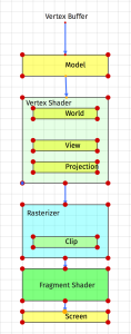
The final responsibility of the vertex shader in a 3D application is to project vertices into a form that can be processed by the rasterizer.
Among other things, The projection matrix modifies a vertex’s W component, which is used by the rasterizer to produce perspective.
The rasterizer is a fixed, non-programmable stage that the GPU executes between the vertex and fragment shaders. It has two purposes:
- Divide each vertex’s XYZ values by W. After the projection matrix, a vertex will most likely have a W that is no longer equal to 1. The rasterizer performs this “perspective divide” by W, leaving a vertex with X,Y and Z values scaled so that the vertex position is scaled down based on it’s depth or distance from the screen.
- Determine a list of fragment locations (roughly the same as a pixel) that fall within the 2x2x2 cube.
- Call the fragment shader for each valid, non-clipped fragment.
Clip-space coordinates are also called Normalized Device Coordinates, or NDC. Any fragment that is rendered will have X,Y, and Z values in the -1:+1 range. Anything outside of that range will be discarded by the rasterizer, before the fragment shader is called.
Screen Space
After the fragment shader executes, and a color is written to the frame buffer, the application will call glSwapBuffers() to present the completed image. In this space, NDCs are mapped to pixel coordinates.
Regardless of the pixel dimensions of the OpenGL window that we’re rendering to, NDCs always range from -1:+1. This is why a non-rectangular window will result in distorted, non-aspect-correct images unless vertices are adjusted to correct for aspect. This is typically done with the projection matrix in the vertex shader.